- VECTRICS VCARVE PRO DESIGN SOFTWARE HOW TO
- VECTRICS VCARVE PRO DESIGN SOFTWARE SERIES
- VECTRICS VCARVE PRO DESIGN SOFTWARE FREE
Please understand that I have personal experience with all of these companies, and I recommend them because they are helpful or I find them useful, not because of the small commissions I might make if you decide to buy something.
VECTRICS VCARVE PRO DESIGN SOFTWARE FREE
If you would like to be notified when the next post comes out why not sign up for our free CNC INFO newsletter or follow me on Twitter SIGN PROJECTS:ĭisclosure: Please note that some of the links below are affiliate links, and at no additional cost to you, I will earn a commission if you decide to make a purchase. Especially, let me know if you find this sort of information helpful and useful. If you have any questions or ideas on topics you would like to see me cover please leave a comment below. It is hard to find accurate information about this process so I hope this will be a good starting point.
VECTRICS VCARVE PRO DESIGN SOFTWARE SERIES
I hope you have been enjoying this tutorial series as much I have enjoyed putting it together. In the next post we will create the final tool paths for the CNC Sign Project and save them to a thumb drive. I use layers quite a bit in Aspire, you should to. Putting the toolpath on a separate layer allows us to make changes to the rest of the design without changing the toolpath. Once you are satisfied with the location of the toolpath, right click it and select move to layer, create new layer.Name the new layer Cow. We can just move the toolpath till it suits our needs. Since we already made a rough sketch of the design we know where the design elements will be on the sign. To move the toolpath around, just double click it and the move it, or re-size it as needed. When you import a toolpath from PhotoVCarve you are only allowed to move it, resize it or mirror it. The photo image you created will load into the preview window of Aspire. Click on FILE, Import, Import PhotoVCarve or Cut3d Toolpath.Select the file you created earlier. Now that the workpiece is defined we can uset the PhotoVCarve toolpath we created in PhotoVCarve last time and import it into Vectric Aspire.

Use the fillet tool to create simple 1″ diameter fillets. Any cuts made by the Z axis will be in a negative direction below the surface of the work piece. It’s just easier for me to think that way. The reason I select this location is so that all X and Y axis movements will be in a positive direction. and the origin point at the lower left hand corner of the material. I then selected the Z zero location as the top of the work piece.
I entered these measurements into the appropriate boxes on the screen. In this case I was using a piece of oak that measured 24″x13.625″x.875″.

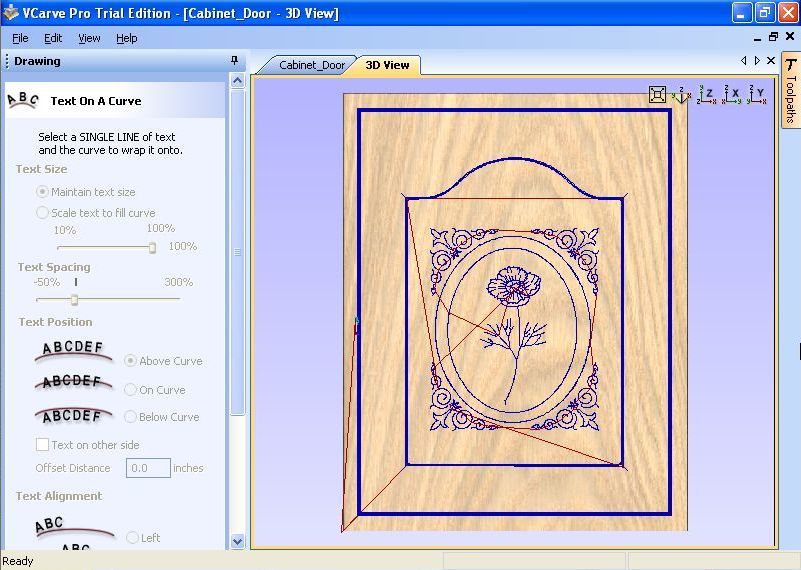
I simply entered the measurements of the actual piece of material we used. The first step we took involved defining the work piece size. Open the Aspire program and select Create a New File icon. Fortunately, the user interface is nearly identical so all the examples-will work in either program.Ī Widgets Defining the work piece I did not use VCarve pro simply because I have Aspire. VCrave pro is a less expensive version of Aspire without the 3D functionality. All the things we are about to do can also be done using Vectric VCarve Pro. For this project we don’t actually need all the power of Aspire. Aspire will allow you to create many types of 3D OBJECTS, VCARVING, photo VCarving and more. Vectric Aspire is the flagship of the Vectric line of products.

In part 4 of the CNC Sign Projects series we talked about creating Photo realistic Vcarvings using Vectric PhotoVCarve.
VECTRICS VCARVE PRO DESIGN SOFTWARE HOW TO
This time we will discuss how to create the rest of the CNC Sign layout using Vectric Aspire.


 0 kommentar(er)
